Product Description
1.Convenient to adjust
2.Wide range of ratio
3.Easy to install
4.high torque
Application Industries:
Our SWL series screw jacks are widely used in the industries such as metallurgy,mining,hoisting and transportation, electrical
power,energy source,constrction and building material,light industry and traffice industry
Screw Jacks in construction
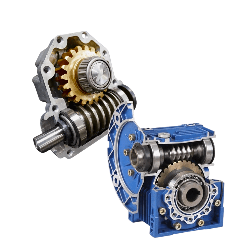
Often found in climbing mechanism of construction,the screw jacks use physical means to raise and lower loads, which typically range from 5 tons to 30 tons. A screw jack is a common type of mechanical jack, which works via a motor and gearbox by an operator. A screw uses the shape of its threads to raise or lower the load, or a traveling nut does the lifting while the screw turns in place. Mechanical jacks are self-locking(not for ball screw), which means that when power is removed from the jack, the screw stays in place until power resumes. This setup makes mechanical jacks safer than their hydraulic counterparts, because users don’t have to fear a loss of power. The main components of screw jacks are; trapezoidal lifting screw also known as lead screw, worm screw, worm gear and gear housing. A worm screw is rotated manually or by a motor. With the rotation of the worm gear, the lead screw in it moves upwards or downwards linearly. The feed rate of the screw depends on the turning speed, the number of teeth of the gears and the size of the screw pitch. In some models of jackscrews, The lifting screw does not move up and down. It only rotates around its axis. A lifting nut (also known as a travelling nut) moves along the lead screw. The lifting nut of the screw jack is made of bronze to decrease friction.
Product Parameters
|
MODEL |
|
SWL2.5 |
SWL5 |
SWL10 |
SWL15 |
SWL20 |
SWL25 |
SWL35 |
|
Maximum lifting force (kN) |
|
25 |
50 |
100 |
150 |
200 |
250 |
350 |
|
Screw thread size |
|
Tr30*6 |
Tr40*7 |
Tr58*12 |
Tr58*12 |
Tr65*12 |
Tr90*16 |
Tr100*20 |
|
Maximum tension (kN) |
|
25 |
50 |
99 |
166 |
250 |
350 |
|
|
Worm gear ratio (mm) |
P |
1/6 |
1/8 |
3/23 |
1/8 |
3/32 |
3/32 |
|
|
|
M |
1/24 |
1/24 |
1/24 |
1/24 |
1/32 |
1/32 |
|
|
Worm non rotating stroke (mm) |
P |
1.0 |
0.875 |
1.565 |
1.56 |
1.5 |
1.875 |
|
|
M |
0.250 |
0.292 |
0.5 |
0.5 |
0.5 |
0.625 |
||
|
Maximum elongation of screw rod under tensile load (mm) |
|
1500 |
2000 |
2500 |
3000 |
3500 |
4000 |
|
|
Maximum lifting height at maximum pressure load (mm) |
The head of the screw rod is not guided |
250 |
385 |
500 |
400 |
490 |
850 |
820 |
|
Lead screw head guide |
400 |
770 |
1000 |
800 |
980 |
1700 |
1640 |
|
|
Worm torque at full load(N.m) |
P |
18 |
39.5 |
119 |
179 |
240 |
366 |
464 |
|
M |
8.86 |
19.8 |
60 |
90 |
122 |
217 |
253 |
|
|
efficiency(%) |
P |
22 |
23 |
20.5 |
|
19.5 |
16 |
18 |
|
M |
11 |
11.5 |
13 |
|
12.8 |
9 |
11 |
|
|
Weight without stroke(kg) |
|
7.3 |
16.2 |
25 |
|
36 |
70.5 |
87 |
|
Weight of screw rod per 100mm(kg) |
|
0.45 |
0.82 |
1.67 |
|
2.15 |
4.15 |
5.20 |
Detailed Photos
SWL Series worm screw Jack:
1.The elevator is a combination of turbine pair and trapezoid screw rod to complete the lifting and lowering of objects. 2.Compact structure, light weight, safety and reliability, long service life, convenient installation
3.Self-locking function in the static state.
|
1. screw rod |
2. nut bolt |
3. cover |
4.Skeleton oil seal |
5.Bearing |
|
6.Worm gear |
7.Oil filling hole |
8.Case |
9.Skeleton oil seal |
10.Cover |
|
11. nut bolt |
12.Bearing |
13.Skeleton oil seal |
14.Bearing |
15.worm |
|
16.Flat key |
17.Bearing |
18.Skeleton oil seal |
19.Cover |
20.Nut bolt |
Product Description
Related Products
Packaging & Shipping
Company Profile
| Standard or Nonstandard: | Nonstandard |
|---|---|
| Application: | Textile Machinery, Garment Machinery, Conveyer Equipment, Electric Cars, Motorcycle, Food Machinery, Marine, Mining Equipment, Agricultural Machinery, Car, Power Transmission |
| Product Name: | Swl Series Worm Gear Lift |
| Input Speed: | 0-1440rpm |
| Ratio: | 6-36 |
| Applicable Industries: | Hotels, Manufacturing Plant, Food & Beverage Facto |
| Samples: |
US$ 50/Piece
1 Piece(Min.Order) | |
|---|

Can you provide examples of machinery that use worm gears?
Worm gears are utilized in various machinery and mechanical systems where precise motion control, high gear reduction ratios, and self-locking capabilities are required. Here are some examples of machinery that commonly use worm gears:
- Elevators: Worm gears are commonly employed in elevator systems to control the vertical movement of the elevator car. The high gear reduction ratio provided by worm gears allows for smooth and controlled lifting and lowering of heavy loads.
- Conveyor systems: Worm gears are used in conveyor systems to drive the movement of belts or chains. The self-locking nature of worm gears helps prevent the conveyor from back-driving when the power is turned off, ensuring that the materials or products being transported stay in place.
- Automotive applications: Worm gears can be found in automotive steering systems. They are often used in the steering gearboxes to convert the rotational motion of the steering wheel into lateral movement of the vehicle’s wheels. Worm gears provide mechanical advantage and precise control for steering operations.
- Milling machines: Worm gears are utilized in milling machines to control the movement of the worktable or the spindle. They offer high torque transmission and accurate positioning, facilitating precise cutting and shaping of materials during milling operations.
- Lifts and hoists: Worm gears are commonly employed in lifting and hoisting equipment, such as cranes and winches. Their high gear reduction ratio allows for the lifting of heavy loads with minimal effort, while the self-locking property prevents the load from descending unintentionally.
- Rotary actuators: Worm gears are used in rotary actuators to convert linear motion into rotary motion. They are employed in various applications, including valve actuators, robotic arms, and indexing mechanisms, where controlled and precise rotational movement is required.
- Packaging machinery: Worm gears find application in packaging machinery, such as filling machines and capping machines. They assist in controlling the movement of conveyor belts, rotating discs, or cam mechanisms, enabling accurate and synchronized packaging operations.
- Printing presses: Worm gears are utilized in printing presses to control the paper feed and the movement of the printing plates. They provide precise and consistent motion, ensuring accurate registration and alignment of the printed images.
These are just a few examples, and worm gears can be found in many other applications, including machine tools, textile machinery, food processing equipment, and more. The unique characteristics of worm gears make them suitable for various industries where motion control, high torque transmission, and self-locking capabilities are essential.

What are the potential challenges in designing and manufacturing worm gears?
Designing and manufacturing worm gears can present several challenges due to their unique characteristics and operating conditions. Here’s a detailed explanation of the potential challenges involved:
- Complex geometry: Worm gears have complex geometry with helical threads on the worm shaft and corresponding teeth on the worm wheel. Designing the precise geometry of the gear teeth, including the helix angle, lead angle, and tooth profile, requires careful analysis and calculation to ensure proper meshing and efficient power transmission.
- Gear materials and heat treatment: Selecting suitable materials for worm gears is critical to ensure strength, wear resistance, and durability. The materials must have good friction and wear properties, as well as the ability to withstand the sliding and rolling contact between the worm and the worm wheel. Additionally, heat treatment processes such as carburizing or induction hardening may be necessary to enhance the gear’s surface hardness and improve its load-carrying capacity.
- Lubrication and cooling: Worm gears operate under high contact pressures and sliding velocities, resulting in significant heat generation and lubrication challenges. Proper lubrication is crucial to reduce friction, wear, and heat buildup. Ensuring effective lubricant distribution to all contact surfaces, managing lubricant temperature, and providing adequate cooling mechanisms are important considerations in worm gear design and manufacturing.
- Backlash control: Controlling backlash, which is the clearance between the worm and the worm wheel, is crucial for precise motion control and positional accuracy. Designing the gear teeth and adjusting the clearances to minimize backlash while maintaining proper tooth engagement is a challenge that requires careful consideration of factors such as gear geometry, tolerances, and manufacturing processes.
- Manufacturing accuracy: Achieving the required manufacturing accuracy in worm gears can be challenging due to their complex geometry and tight tolerances. The accurate machining of gear teeth, maintaining proper tooth profiles, and achieving the desired surface finish require advanced machining techniques, specialized tools, and skilled operators.
- Noise and vibration: Worm gears can generate noise and vibration due to the sliding contact between the gear teeth. Designing the gear geometry, tooth profiles, and surface finishes to minimize noise and vibration is a challenge. Additionally, the selection of appropriate materials, lubrication methods, and gear housing design can help reduce noise and vibration levels.
- Efficiency and power loss: Worm gears inherently have lower efficiency compared to other types of gear systems due to the sliding contact and high gear ratios. Minimizing power loss and improving efficiency through optimized gear design, material selection, lubrication, and manufacturing accuracy is a challenge that requires careful balancing of various factors.
- Wear and fatigue: Worm gears are subjected to high contact stresses and cyclic loading, which can lead to wear, pitting, and fatigue failure. Designing the gear teeth for proper load distribution, selecting appropriate materials, and applying suitable surface treatments or coatings are essential to mitigate wear and fatigue issues.
- Cost considerations: Designing and manufacturing worm gears can be cost-intensive due to the complexity of the gear geometry, material requirements, and precision manufacturing processes. Balancing performance requirements with cost considerations is a challenge that requires careful evaluation of the gear’s intended application, performance expectations, and budget constraints.
Addressing these challenges requires a comprehensive understanding of gear design principles, manufacturing processes, material science, and lubrication technologies. Collaboration between design engineers, manufacturing experts, and material specialists is often necessary to overcome these challenges and ensure the successful design and production of high-quality worm gears.

Can you explain the concept of worm and worm wheel in a worm gear?
In a worm gear system, the worm and worm wheel are the two primary components that work together to transmit motion and power. Here’s an explanation of the concept:
Worm:
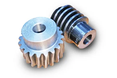
The worm is a cylindrical shaft with a helical thread wrapped around it. It resembles a screw with a spiral groove. The helical thread is called the worm’s thread or worm thread. The worm is the driving component in the worm gear system.
When the worm rotates, the helical thread engages with the teeth of the worm wheel, causing the worm wheel to rotate. The angle of the helical thread creates a wedging action against the teeth of the worm wheel, resulting in a high gear reduction ratio.
One important characteristic of the worm is its self-locking nature. Due to the angle of the helical thread, the worm can drive the worm wheel, but the reverse is not true. The self-locking feature prevents the worm wheel from backdriving the worm, providing a mechanical brake or holding position in the system.
The worm can be made from various materials such as steel, bronze, or even plastics, depending on the application requirements. It is often mounted on a shaft and supported by bearings for smooth rotation.
Worm Wheel:
The worm wheel, also known as the worm gear, is the driven component in the worm gear system. It is a gear with teeth that mesh with the helical thread of the worm. The teeth on the worm wheel are typically helical and cut to match the angle and pitch of the worm’s thread.
As the worm rotates, its helical thread engages with the teeth of the worm wheel, causing the worm wheel to rotate. The rotation of the worm wheel is in the same direction as the worm’s rotation, but the speed is significantly reduced due to the high gear reduction ratio of the worm gear system.
The worm wheel is usually larger in diameter compared to the worm, allowing for a higher gear reduction ratio. It can be made from materials such as steel, bronze, or cast iron, depending on the application’s torque and durability requirements.
Together, the worm and worm wheel form a compact and efficient gear system that provides high gear reduction and self-locking capabilities. They are commonly used in various applications where precise motion control, high torque, and compactness are required, such as elevators, steering systems, and machine tools.


editor by CX 2023-09-07